Global layout

 +86 769 2366 8529





Time:2026-10-17 Views:45
60V 100Ah LiFePO4 Electric Tricycle Battery:Design,Application and Engineering Guidelines
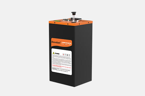
In scenarios such as short-distance freight, urban-rural distribution, yard transportation and scenic area passenger transport, electric tricycles are widely adopted thanks to flexible loading and low operating costs. Frequent heavy loads, repeated start-stop cycles and complicated road conditions impose high requirements on power batteries in terms of continuous output, vibration resistance and safety stability. The 60V 100Ah LiFePO4 electric tricycle battery, leveraging the excellent thermal stability and long cycle life of lithium iron phosphate materials, has become one of the mainstream power solutions for heavy-duty electric tricycles. This battery pack is not a simple stack of cells. It is a complete power system covering cell selection, module layout, battery management system, enclosure protection, thermal management and reliability verification. It must match the output characteristics of tricycle controllers and motors, frame installation space and complex road conditions to guarantee driving range, climbing power, long-term operational stability and driving safety.
A single LiFePO4 cell has a nominal voltage of 3.2V. To build a 60V platform, a 20-series configuration is generally adopted. The cell charge cut-off voltage is 3.65V, and the upper charging limit of the whole battery pack is approximately 73V. Its nominal capacity is 100Ah with total energy of roughly 6000Wh. Compared with traditional lead-acid batteries, LiFePO4 packs of the same specification are lighter, normally achieve more than 2000 charge-discharge cycles, and show milder capacity fading over long-term operation, which fits commercial tricycles requiring daily frequent charging and discharging. Nevertheless, LiFePO4 suffers from reduced discharge capability at low temperatures. For deployment in cold northern regions, preheating structures need to be integrated into the solution to mitigate capacity loss under low-temperature environments. During vehicle matching, continuous current and peak discharge requirements shall be calculated according to vehicle load, maximum climbing gradient and average driving speed to determine cell discharge rate and strike a balance among battery volume, self-weight, range and power output.
Cell selection and module layout lay the foundation for PACK design. Grade A prismatic LiFePO4 cells with good consistency are preferred for the whole battery pack. Mixing cells from different batches, capacities or internal resistance values is not recommended. Poor cell consistency will cause gradual voltage divergence among series cells after long-time heavy-duty operation of the vehicle, resulting in premature degradation of individual cells. In severe cases, local heat generation may occur and bring potential safety hazards. The 20-series structure meets the 60V voltage platform. Single 100Ah cells directly form modules without parallel connection of multiple cells, reducing the number of busbars and solder joints and lowering heat points under high-current operation. Cell arrangement must adapt to the reserved battery compartment on the tricycle frame. Some vehicle models have narrow or height-limited compartments, requiring adjustment of module orientation, together with epoxy insulation plates and buffer foam for isolation and shock absorption. Inside modules, copper busbars realize series connection. Busbar thickness shall match maximum operating current to reduce loop internal resistance and temperature rise. Meanwhile, evaluation on the overall center of gravity of modules is required. Excessive battery pack weight or offset center of gravity will impair braking stability and steering handling of tricycles, a factor that cannot be overlooked in heavy-duty vehicle design.
The battery management system (BMS) serves as the core control unit of the battery pack and the key to safe operation. The BMS integrates protection functions for overcharge, overdischarge, overcurrent, short circuit and overtemperature. It collects real-time voltage and multi-point temperature data of each series cell and performs passive or active balancing to prevent individual cells from hitting protection thresholds in advance and limiting vehicle power output. A heavy-duty tricycle generates large impulse current during start-up and hill climbing. Therefore, BMS current sampling and power protection thresholds need dedicated calibration instead of directly adopting protection parameters for light two-wheelers. Depending on vehicle demands, the BMS can be equipped with Bluetooth or RS485 communication interfaces to upload battery status data such as remaining capacity, cell temperature and fault codes for dashboard display, fleet background monitoring and fault diagnosis. For fleets of tricycles, smart BMS records long-term charge-discharge data, predicts battery degradation trends and schedules maintenance in advance to reduce losses caused by vehicle shutdown. Charge and discharge protection thresholds of the BMS must match LiFePO4 cell characteristics. Incorrect adoption of NMC battery parameters will trigger abnormal protection logic and endanger battery safety.
Housing structure, sealing protection and anti-vibration design directly determine the reliability of battery packs under complicated road conditions. Most electric tricycles run on rural roads, construction sites and unpaved yard surfaces, enduring continuous bumps and vibration, as well as rain wash, mud splashes and dust accumulation. Sheet metal or aluminum alloy is commonly used for enclosures. Aluminum housings provide better heat dissipation and suit heavy-duty freight tricycles with sustained high-current output; sheet metal enclosures offer cost advantages for regular passenger and light-load transport vehicles. The sealing structure can generally reach IP67 rating to resist temporary water immersion and rain spray. Pressure relief valves are reserved on the shell to balance internal air pressure and avoid shell deformation or pressure accumulation caused by temperature fluctuation. Buffer foam fills the space around modules, together with metal brackets for rigid fixing to absorb road shocks and lower risks of desoldering of tabs and busbars from long-term vibration. Mounting holes and fixing brackets on the exterior of battery packs can be matched according to frame mounting points of tricycles to secure the battery firmly and reduce relative displacement during travel.
Thermal management design is also essential. Although LiFePO4 has superior thermal stability compared with other lithium chemistries, the battery will continuously generate heat when a tricycle climbs slopes under heavy load. Excessive temperature difference among multiple series cells inside modules will accelerate consistency degradation and shorten the service life of the whole pack. Conventional schemes rely on natural heat dissipation through metal housings. For heavy-duty models working under continuous high power, thermal silicone pads can be added to transfer heat from modules to the outer shell. Multiple temperature sensors are placed inside the battery pack to collect temperature data in different module zones. When temperature exceeds the safe range, the BMS limits charge and discharge power for thermal protection. For low-temperature regions, low-temperature preheating modules can be integrated inside modules. The heater activates when ambient temperature is low to improve cell activity, enhance cold start and discharge performance and expand the applicable range of the battery in cold climates.
Connectors, wire harnesses and charging interfaces belong to supporting design items and must match the vehicle electrical system. Connectors need vibration resistance, waterproof performance and high current tolerance to avoid abnormal connector heating under heavy high-current conditions. Wire harness gauge is selected according to maximum continuous discharge current to reduce line voltage drop and heat generation. Interface positions and plug orientation can be adjusted based on frame wiring space to simplify vehicle assembly and facilitate later maintenance. Before the battery is put into use, charger parameters must match the BMS of the battery pack. The output voltage and maximum charging current of the charger should comply with battery specifications. Mismatched parameters may lead to overcharging or insufficient charging and accelerate battery aging.
After prototype fabrication, a full set of reliability verification tests shall be carried out to verify stability under real working conditions. Test items include ambient temperature charge-discharge cycling, high and low temperature charge and discharge, random vibration test, mechanical shock test, water and dust resistance test, short-circuit protection test, extrusion test, etc., simulating tricycle operation on various road surfaces and climates. The tests identify potential risks such as structural loosening, sealing failure, thermal management defects and abnormal BMS protection logic, supporting iteration of structural and electrical design. After passing prototype tests, pilot batch production is launched to evaluate assembly consistency. Mass delivery starts only after stable production processes are confirmed.
Compliance certification is an indispensable part of battery project rollout. According to regulations of target markets, battery packs need relevant safety and EMC certifications to meet requirements for transportation and market access. Different regions set distinct standards for power batteries and dangerous goods transportation. Such requirements should be considered in the early design phase to prevent project delays and extra costs caused by certification failure after prototype completion. Many buyers only focus on voltage and capacity during selection and ignore system matching. If BMS protection thresholds, harness specifications and connector current ratings mismatch motor controllers, the vehicle will suffer poor climbing performance, false protection triggering and connector overheating even if cell parameters meet requirements. The self-weight and installation position of the battery pack will also change the vehicle center of gravity and require joint evaluation with the vehicle structural team.
For daily operation and maintenance, this type of battery pack needs standardized usage. Long-term full-charge storage should be avoided; medium state of charge is recommended for long parking periods. Connectors and shell sealing shall be inspected regularly and the shell checked for collision damage. Once shell swelling, abnormal heating or peculiar odor is detected, the battery must stop using immediately and receive professional inspection. Operating fleets can leverage BMS monitoring to export charge-discharge data periodically, track battery degradation and conduct maintenance in advance to reduce breakdown risks on the road.
To sum up, the 60V 100Ah LiFePO4 electric tricycle battery is a complete power system solution for heavy-duty short-distance transportation rather than a simple combination of standard cells. Every stage, from cell screening, module series-parallel arrangement, BMS protection strategy, shockproof and waterproof housing structure, thermal management design to reliability testing and compliance certification, requires targeted optimization for electric tricycles characterized by heavy loads, frequent start-stop cycles and bumpy roads. For urban-rural freight, yard transportation and scenic passenger transport, this battery solution achieves a balance among safety, cycle life, power output, driving range and installation dimensions. It fully leverages the material strengths of LiFePO4 including high safety and long cycle life, adapts to power upgrade demands of different electric tricycles and supports continuous iteration of short-distance electric transport equipment.
Be the first to receive our latest news, how-to user guides,
and exclusive deals! Subscribe now.

 Headquarter Address:10F, Building 25, N0. 179 Fengguan, Dongshen Road, Dongguan, Guangdong
 Factory Address:Building 3, Area D, Shengyang Science and Technology Industrial Park, East District of Suichuan County Industrial Park, Ji'an, Jiangxi
 Headquarter Telephone No.:+86 769 2366 8529
Factory Telephone No.:+86 796 6111618
 Contact Person:Kevin Chen
 Email Address:chen@xpower-world.com