Global layout

 +86 769 2366 8529





Time:2026-11-10 Views:119
When the Battery Starts Speaking Data: CAN Interfaces on LiFePO4 Packs and the Points That Matter at Integration
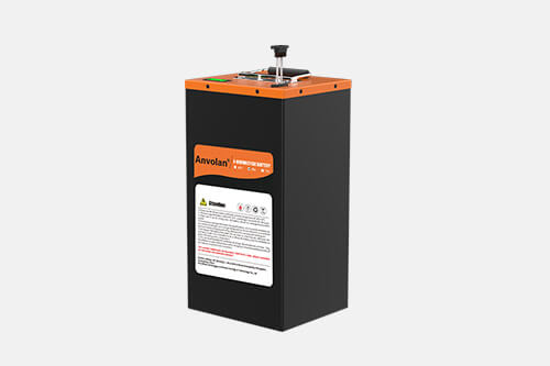
In AGVs, low-speed delivery vehicles, motorhomes, and small energy-storage cabinets, 48-volt LiFePO4 packs have become a standard fitting. What moves these machines from working to working well is usually not a few extra amp-hours but whether the pack can state its condition clearly to a host controller and accept instructions from it. This article takes the 48V LiFePO4 battery with CAN communication as its subject and looks at what the interface offers, what to settle at the protocol layer, and which details go wrong when the pack is integrated into a system.
1. Matching the 48-Volt Platform to LiFePO4
Forty-eight volts was originally a lead-acid convention, usually four 12-volt batteries in series. A LiFePO4 replacement mostly uses a 16-cell series string: 51.2 V nominal, about 58.4 V at full charge, and a discharge cut-off around 40 V. Controllers, inverters, and chargers have to be configured for that window, because lead-acid thresholds produce an alarm the moment the pack is full or a cut-off far too early.
Capacity and rate follow the load. Continuous discharge usually sits at 0.5C to 1C while instantaneous current is higher, so the instantaneous allowable discharge current should be reported as its own parameter, letting the host limit power rather than waiting for the protection board to trip.
Where the temperature is sampled has to be stated in the protocol: cell surface, module interior, or enclosure. Otherwise the host reads a number that does not correspond to the actual hot spot.
2. What the CAN Interface Delivers
Observable state. Cell voltages, module temperatures, pack voltage, current, SOC, SOH, and cycle count are broadcast periodically, so the host needs no extra sensors.
Controllable outputs. Charge and discharge current limits, contactor control, balancing enable, sleep and wake can all be sent by message, which allows scheduling by operating condition.
Coordinated paralleling. Parallel packs negotiate a master-slave arrangement over CAN, with the master aggregating current and SOC, which avoids the round-robin tripping that differing thresholds otherwise cause.
Diagnosable faults. Overvoltage, undervoltage, overtemperature, excessive temperature spread, insulation faults, and communication timeout should each carry a defined fault code and severity, so the field technician can locate the problem instead of seeing a single red lamp.
3. Key Choices at the Protocol Layer
Physical layer first. Bit rates of 125k, 250k, and 500k are common, and higher rates are less forgiving of harness and termination quality; a multi-node bus carries a 120-ohm terminator at each end, and intermediate nodes must not add another.
Message identifiers need planning. Eleven-bit standard frames suit small systems, while 29-bit extended frames allow a wide numbering range; with CANopen or J1939, node IDs, PGNs, and signal definitions have to be allocated in advance.
The data mapping document has to be complete. Signal name, start bit, length, byte order, scale factor, unit, and invalid value — miss one and every integration session becomes guesswork. A DBC file with a written description alongside it is the more professional route.
Periods and timeouts must be agreed. Frame period, heartbeat timeout, and the degradation strategy after communication loss all need stating, or the host cannot tell what "no data received" means.
Isolation and grounding cannot be skipped. The transceiver should be galvanically isolated from the pack circuitry, and the shield should have a single ground reference, or common-mode noise produces errors and intermittent dropouts.
4. Common Problems at Integration
Address collision. After paralleling or a part swap, duplicated node IDs make messages overwrite each other, showing up as jumping values or a dead bus; numbering should be fixed at assembly and marked on the label.
Protocol version mismatch. Batches of the same model using different mapping tables produce misread data after replacement, so the document should carry a version number linked to the serial record.
Charger handshake. Some chargers start only after the pack reports allowable charge current and maximum voltage, and a missing handshake is then read as a battery fault when the protocol simply does not line up.
Sleep and wake. A pack left standing enters a low-power state, and if wake depends on CAN activity, the host can be powered while the pack still sleeps, so the wake condition and delay need to be specified.
5. Acceptance and Commissioning
Check the harness before power-up. Reversed CAN_H and CAN_L, missing terminators, and a broken shield account for most site faults.
Replay the whole sequence with a bus tool. From rest through charge, discharge, protection trip, and communication loss, log the messages and fault codes item by item and confirm they match the document.
Inject one fault. Pull the bus cable, short the terminator, simulate an excessive temperature spread, and see whether the system degrades rather than stopping outright.
Keep the logs. Commissioning traffic archived by date saves a great deal of time later.
Be the first to receive our latest news, how-to user guides,
and exclusive deals! Subscribe now.

 Headquarter Address:10F, Building 25, N0. 179 Fengguan, Dongshen Road, Dongguan, Guangdong
 Factory Address:Building 3, Area D, Shengyang Science and Technology Industrial Park, East District of Suichuan County Industrial Park, Ji'an, Jiangxi
 Headquarter Telephone No.:+86 769 2366 8529
Factory Telephone No.:+86 796 6111618
 Contact Person:Kevin Chen
 Email Address:chen@xpower-world.com