Global layout

 +86 769 2366 8529





Time:2026-10-27 Views:78
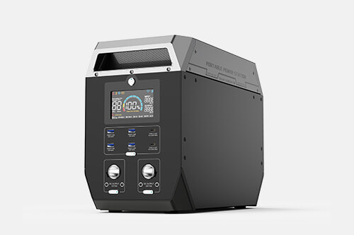
Emergency power stations support power restoration, field operations, disaster response and temporary power backup. Their reliability does not depend on cells or inverters alone. Instead, it is shaped by a connected sequence of business and manufacturing stages, each with defined controls. The workflow covers requirement communication, solution definition, component selection, incoming inspection, assembly, in-line testing, reliability validation, packaging, delivery, after-sales service and corrective-action closure. Every stage carries its own quality objectives and traceability rules. Emergency power equipment has distinct characteristics: many units sit idle for long periods on standby and must operate reliably the moment they are activated. This imposes stricter requirements on consistency, redundancy and long-term stability than consumer portable power products.
Requirement alignment and solution definition form the earliest upstream stage and set whether the final product fits emergency use cases. This phase is not about immediately selecting cells or inverter hardware. It clarifies operational boundaries: typical load types, continuous and peak power, required runtime, ambient temperature range, whether the unit remains stationary in storage or moves frequently, communication requirements, safety certifications and delivery schedules. Emergency scenarios vary widely. Some units stay indoors for mains failure backup, others travel with rescue teams into humid, thermally unstable outdoor zones, and some serve vehicle-mounted field repair crews. Each use case demands unique protection thresholds, thermal designs, battery balancing schemes and ingress protection grades. Engineers translate load characteristics into quantifiable specifications, including derating rules, standby loss limits and alarm logic, and produce datasheets, schematics and BMS strategy documents. Missing or oversimplified assessments at this stage lead to mismatched hardware. Even perfectly built units may fail when emergency power is truly needed.
Component selection and specification confirmation establish the foundational quality baseline. A complete station integrates dozens of parts: battery cells, battery management systems, inverter power boards, MPPT charge controllers, communication modules, connectors, wiring harnesses, enclosures, fuses and temperature sensors. Selection cannot rely solely on nameplate ratings. Engineers must evaluate long-term stability under the emergency-product profile of extended storage and sporadic activation. For cells, key concerns include cycle fade, self-discharge and voltage drift. Power semiconductors require voltage and current margin against sudden load surges. Connectors and terminals must maintain stable contact through vibration, repeated plugging and humid conditions. Insulation materials, sealants and enclosure plastics are screened for ageing resistance, flame retardancy and thermal tolerance. Alternate parts require equivalent validation before approval. A common risk at this stage is choosing components rated exactly at the limit to cut cost. These may pass short-term tests but degrade rapidly after months of storage or thermal cycling and fail on demand.
Incoming quality inspection is the first barrier preventing nonconforming materials from entering production. Critical components are sampled or fully inspected against predefined criteria agreed during component qualification. Cell inspection covers capacity, internal resistance, open-circuit voltage and appearance, with strict sorting for batch consistency. BMS and inverter boards undergo spot power-on checks for basic functions and protection thresholds. Harness inspection verifies conductor gauge, crimp pull strength and dielectric withstand. Enclosure checks validate dimensional tolerances, sealing geometry and flame-retardant marking. Inspection records support batch traceability. Emergency stations demand tighter cell matching. Voltage and internal resistance spread left unfiltered at receiving cannot be easily corrected after assembly and create risks of overheating, premature shutdown and reduced usable capacity. Failed materials are segregated, reviewed and returned; high-risk nonconforming stock must not be released for production.
SMT assembly and board-level debugging apply to BMS, inverter and MPPT control circuits. These circuit boards handle control and power conversion. Soldering quality, component placement and PCB routing directly affect electromagnetic immunity, temperature rise and protection response. Production controls include solder paste management, reflow profile calibration and placement accuracy to avoid cold joints, insufficient solder or misaligned devices. After soldering, each PCB is debugged independently before integration. Technicians verify voltage sensing, current sensing, temperature sampling, overvoltage and overcurrent protection, and MOSFET drive behaviour. Board-level testing isolates faults early, when repairs are simpler. Many field issues such as false protection, measurement drift and unstable inversion originate from poor solder joints or component tolerance deviation. Emergency systems require precise sampling. Cumulative sensing errors distort state-of-charge estimation during long standby periods and cause the controller to misjudge remaining energy.
Cell grouping and battery PACK assembly build the energy storage core. Pre-sorted cells are matched into series-parallel configurations defined by the design. Open-circuit voltage, internal resistance and capacity differences within each pack are tightly controlled. Next come tab welding, busbar installation, temperature sensor mounting, BMS wiring and insulation placement. Welding is a critical control point. Laser or ultrasonic welding parameters are stabilized to prevent incomplete fusion, burn-through or weak contact points that heat up under surge current. Temperature sensor location and fixation are standardized; sensors placed too far from heat sources delay overtemperature protection, while excessive sensors raise cost. Insulation sheets, flame-retardant padding and cable ties prevent wire movement and insulation damage caused by transport vibration. Finished PACKs go through separate charge-discharge cycling, balancing validation and protection calibration. Only qualified battery packs move on to full-system integration.
System integration combines the battery PACK, inverter module, charger, ports, display and housing into one complete unit. This stage involves mechanical alignment, harness routing, sealing and thermal assembly. Cables are routed away from high-temperature power zones to reduce electromagnetic interference. Gaskets and waterproof connectors are fitted properly to maintain ingress ratings. Thermal pads and airflow channels must be fully seated to eliminate local hotspots. Work instructions standardize screw torque and connector locking order to avoid missing or loose fasteners. Emergency stations carry many ports: AC output, solar input, vehicle charging and DC outlets. Assemblers verify markings to prevent reverse wiring. Before power-up, a static insulation test confirms no short circuits and adequate isolation.
End-of-line functional testing and burn-in form the core factory validation stage and simulate emergency operating conditions. The workflow includes static function checks, dynamic load testing and continuous burn-in. Static tests validate displays, buttons, alarms, communication and port voltages. Dynamic testing uses adjustable electronic loads to simulate light load, rated continuous load and short surges, monitoring inverter waveform, voltage stability and protection triggering. Burn-in runs the unit under defined load for a set duration while logging temperature, voltage and current. This reveals latent defects such as marginal solder joints, thermally drifting components and intermittent contact faults that only appear under heat. For emergency models, standby simulation is added: units are fully charged, rested and remeasured for remaining capacity and cell imbalance to verify self-discharge and balancing. Many general power products shorten burn-in cycles, but emergency stations require adequate loaded runtime to filter units that perform normally in brief tests and fail under sustained operation.
Reliability and safety type testing differs from routine production sampling. It is a project-level confirmation performed at sample phase or after major material or process changes. Test suites cover temperature cycling, damp heat, salt spray, vibration, shock, drop, hipot, leakage current and flammability evaluation. These replicate rough transit, wide outdoor temperature swings, humidity and accidental impact to validate structural integrity, electronics, sealing and battery robustness. Safety testing follows standards for the target market, covering earthing, electric-shock prevention, fire control and hazardous-energy limits. Type testing is not performed on every unit, but its results decide whether a material or process batch is acceptable. Failure triggers root-cause reviews across selection, assembly and welding stages. Production resumes only after corrective actions pass retesting.
Packaging, marking and warehousing protect product condition through delivery. Emergency stations are heavy and battery-equipped. Packaging must provide cushioning, tip-over resistance and moisture control to shield internal solder joints and connectors during long-distance vibration. Permanent markings include ratings, hazard notices, emergency operating instructions, serial numbers and batch codes for traceability. Each serial number links to test logs and material batches, enabling backward investigation if problems arise later. Warehousing controls temperature and humidity to avoid accelerated cell self-discharge and ageing. A final pre-shipment check verifies appearance, screen operation and basic output. Delivery documentation includes datasheets, user guides and troubleshooting checklists. End users responding to outages are often non-specialists, so clear guidance reduces improper field operation.
After-sales feedback, failure review and continuous improvement close the control loop and feed optimizations back into all upstream stages. Failures from real blackouts and rescue deployments provide high-value field data. Returned units are disassembled and analysed to separate root causes: component failure, manufacturing defect, test escape, application mismatch or user error. Formal corrective actions update controls upstream. If connector contact failures recur, incoming checks and assembly torque rules are revised. If voltage imbalance grows rapidly during standby, cell sorting and balancing logic are improved. Lessons are added to test libraries, and newly identified risks become mandatory production test items. Many manufacturers stop at replacement repairs without deep root-cause analysis, allowing identical faults to reappear and undermining emergency readiness.
All stages are interdependent. Weaknesses upstream amplify downstream risks. Overly aggressive component selection defeats careful assembly. Loose cell sorting burdens later testing. Shortened burn-in leaves hidden defects to surface during an emergency. The core value of an emergency power station is reliable activation when needed. This cannot rely on final testing alone. Quality must be controlled across the full chain: concept, sourcing, production, validation, storage and post-failure review. Consistent standards at every stage reduce the risk of power failure when backup energy matters most.
Be the first to receive our latest news, how-to user guides,
and exclusive deals! Subscribe now.

 Headquarter Address:10F, Building 25, N0. 179 Fengguan, Dongshen Road, Dongguan, Guangdong
 Factory Address:Building 3, Area D, Shengyang Science and Technology Industrial Park, East District of Suichuan County Industrial Park, Ji'an, Jiangxi
 Headquarter Telephone No.:+86 769 2366 8529
Factory Telephone No.:+86 796 6111618
 Contact Person:Kevin Chen
 Email Address:chen@xpower-world.com